I bought a Kantronics KPC-3 TNC at the Elkhorn Valley ARC Hamfest in November 2021. I already own a USB version of the KPC-3+, but I figured owning a second TNC would be a good idea. I decided to make a radio control cable so I can use it with my ICOM IC-V8000 2M mobile.
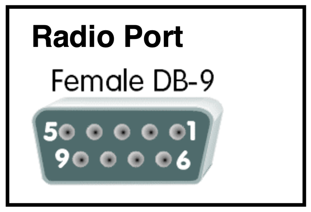
The first thing I had to do was find a pin-out diagram for the DB9 connector on the back of the KPC-3. Searching the web I found a document that had plenty of information about the pin-outs for both connectors on the back of the KPC-3. The document was for the KPC-3+ (the successor to the KPC-3) but I took a gamble that the pin-outs hadn’t changed. And I was right.
TNC Connection
Although the serial port connector has 9 pins, only four are needed to control the radio:
| Pin # | Purpose |
| 1 | Audio to Radio (TX) |
| 3 | PTT |
| 5 | Audio from Radio (RX) |
| 6 | Ground |
Radio Connection
The next task was to do the same thing for the IC-V8000. The radio uses an RJ-45 8-pin connector for its microphone. Again, searching the web I found the user guide for the radio which contained the pinout for the microphone.
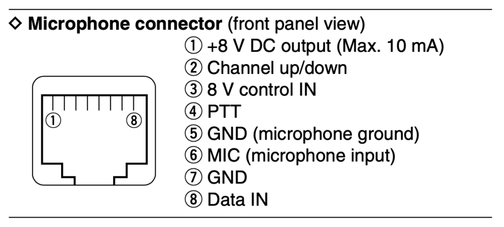
The microphone doesn’t contain a wire for the receive audio, so that would have to come from the 3.5mm audio jack on the back of the radio.
Putting It Together
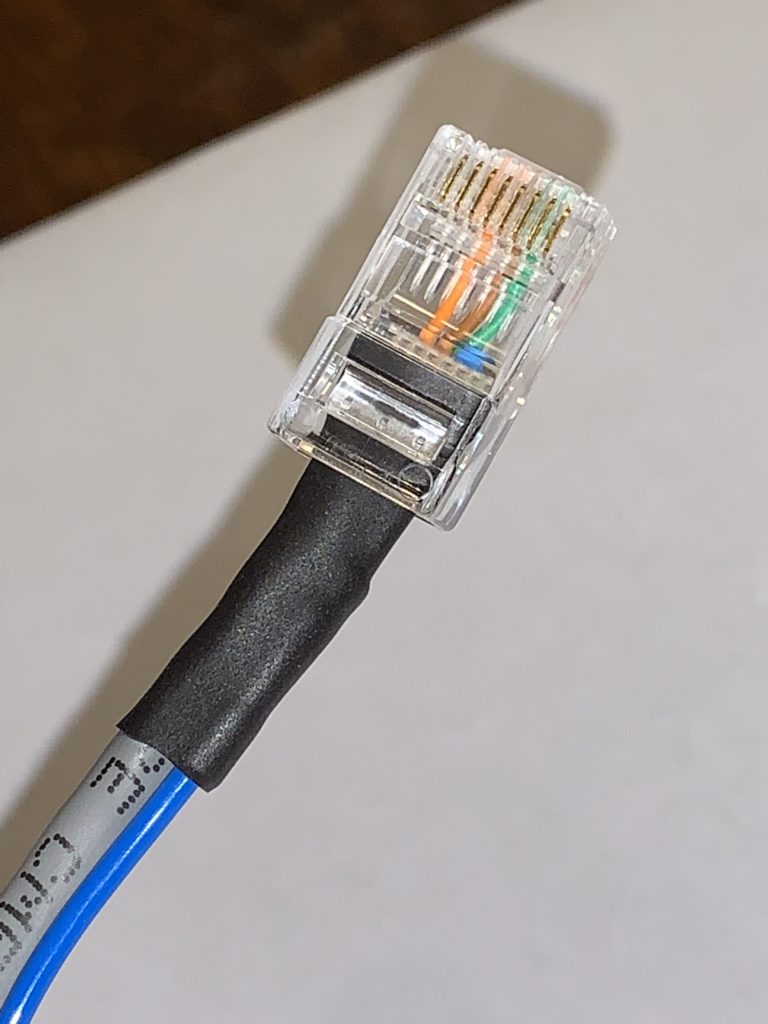
Since the radio uses an RJ-45 connector, I decided to use Cat5e ethernet cable (that I already had on hand) for my assembly. Ethernet cable has 8 contacts but I only needed 4; so I simply snipped off the other 4 I didn’t use. I created a matrix to reference while I assembled everything.
| Wire Color | Function | Radio RJ-45 Pin | KPC-3 DB9 Pin |
| Brown | TX Audio | 6 | 1 |
| Orange | PTT | 4 | 3 |
| Blue | RX Audio | audio jack tip | 5 |
| Green | Ground | 7 | 6 |
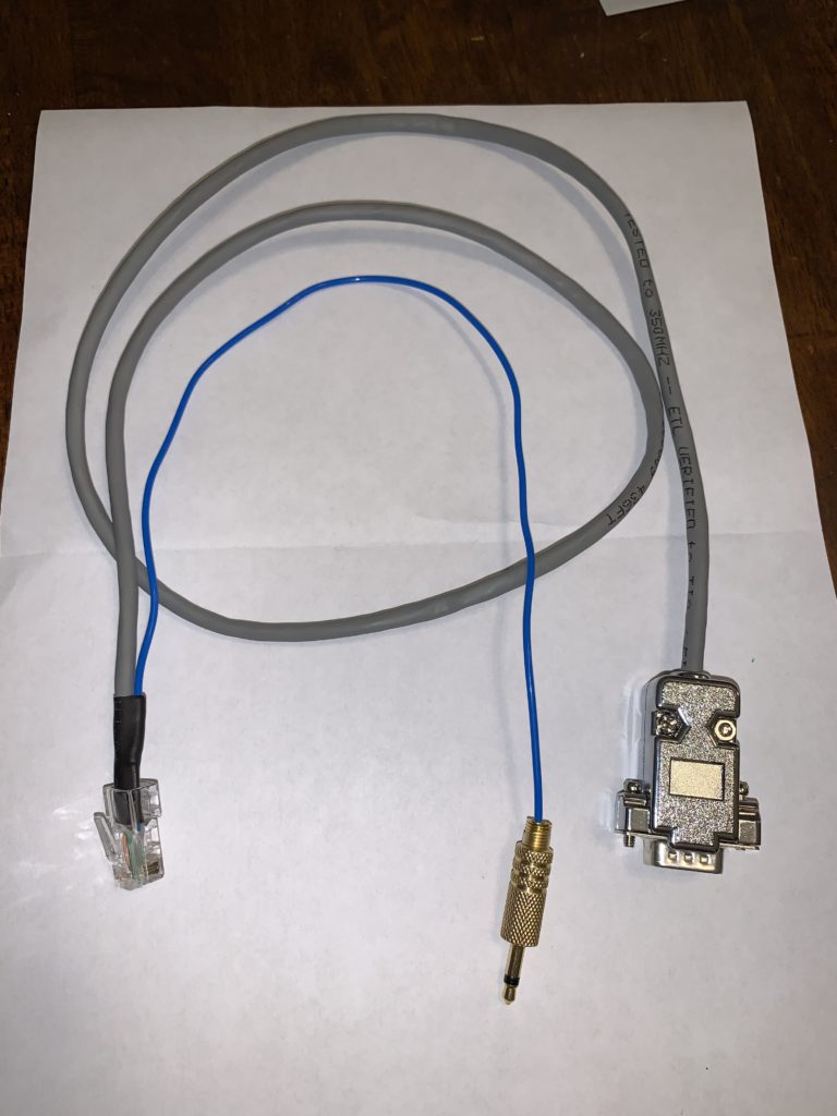
I already owned a male DB9 assembly end. I soldered the proper colored wires to the proper pin numbers on the connector and carefully screwed the whole assembly together. This was a task that required 3 hands so I incorporated the help of my teenage son.
The RJ45 connector only needed 3 wires in it. The fourth needed to have a longer length of wire soldered onto it with a 3.5mm audio jack also soldered onto the other end. This wire will go to the audio jack on the back of the radio.
This was my first ever cable assembly. I was meticulous and it went a lot slower than I thought it would. I’m happy to report that the cable works great. The best part is that I already owned nearly all the parts needed to assemble it. The only thing I didn’t already have on hand was the TS audio jack. A big thanks to WD0BFO for permanently loaning me the audio jack!